I’ve said it before and I’ll say it again: teaching electric circuits is hard.
Providing your students with a conceptual model can, in my opinion, be immensely helpful. In recent years, I have used what I call the Coulomb Train Model (CTM). It is essentially a variation on the “stiff chain” analogies that some researchers have argued as being particularly useful in developing students’ understanding.
One reason why I like the CTM is that it provides a physical picture to aid students’ comprehension of many of the electrical equations needed at GCSE.
Of course, any analogy or model will have its flaws, but on the whole I think the CTM has fewer than many of its rivals!
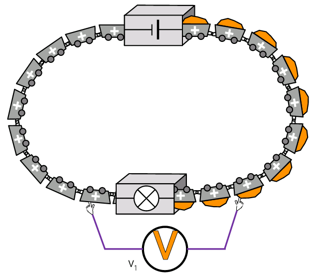
Essentially, the CTM pictures an electric circuit as a continuously moving chain of postively-charged “trucks” called coulombs that carry energy from the cell to (say) the bulb. In the diagram below, they should be pictured as moving clockwise.

The coulomb is, of course, the S.I. unit of electric charge, so rest assured that there is method in the apparent madness of naming our “trucks” with a word that would be unfamiliar to most of our students.
Charge flow = current x time

Charge flow = number of coulombs that pass a given point in time.
Current = number of coulombs that pass by in one second (i.e. current = charge flow / time).
In other words, an ammeter counts the coulombs passing by in one second. The ammeter only “sees” the coulombs and does not register how much (or how little) energy each one contains. Therefore current I1 and current I2 are equal.
The ammeters are shown as being semi-transparent in order to provide a visual cue that they are low resistance devices.
Energy transferred = charge flow x potential difference
On the CTM, potential difference can be pictured as energy being added to, or removed from, each coulomb.
For example, if one joule is removed from each coulomb as they pass through the bulb, the potential difference across the bulb is one volt. If one joule is added to each coulomb as they pass through the cell, then the potential difference (or e.m.f.) across the cell is one volt.
The total energy transferred from (say) ten coulombs passing through the bulb would be charge flow (10 coulombs) x potential difference (1 volt) = 10 joules.
The white gloves on the voltmeter are intended to be reminiscent of the white gloves of a snooker referee.

The intention is to disrupt the flow of the coulombs as little as possible and so this is a visual reminder that a voltmeter is a high resistance instrument.
To emphasise the fact that potential difference is an “energy difference”, challenge students to predict the reading on this voltmeter.

The potential difference V3 is, of course, zero since there is no transfer of energy to or from the coulombs.
Current in Series and Parallel Circuits
I think the CTM can be really effective in allowing students to a see a comprehensible physical analogue of the circuits.

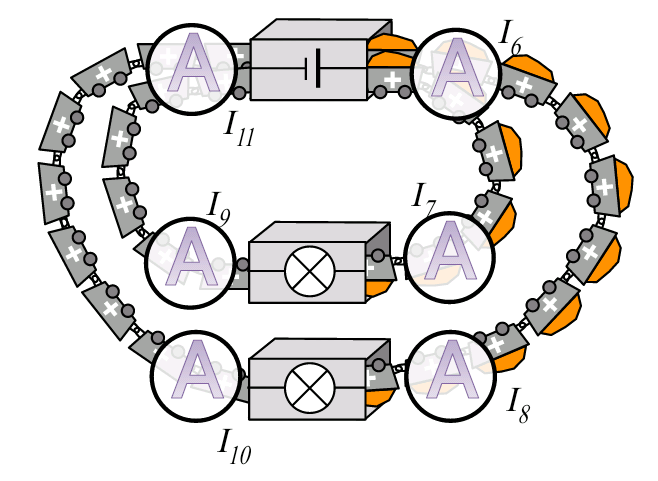
For example, I3 = I4 = I5 = 0.5 amps; I6 = I11 = 2 amps; and I7 = I8 = I9 = I10 = 1 amp.
Potential difference in series and parallel circuit
Equally, I think the CTM can give a comprehensible physical picture of the situation.

In this case (assuming the the cell has a p.d. of 1 V and the bulbs are identical), V4 = V5 = 0.5 V.

In the parallel circuit, each bulb tranfers one joule of energy from each bulb, and so the potential difference across each bulb is one volt.
You can read more on the CTM here.
You can also a find a booklet to support teaching electric circuits using the CTM here.

Reblogged this on The Echo Chamber.
Thanks for sharing this – and the diagrams are particularly interesting! I do like the use of a *continuous* chain of carriages, with no engine on board. Arguably what you’re describing is more like a chairlift or cable car, with the mechanism causing movement separate to the moving objects, than the train often used in such models.
The difficulty I have is that this still leads to an understanding of energy as a discrete substance that can and must be carried (by coulombs, in this case). This model cannot explain energy transfer by a.c., which I’ve always felt is a huge advantage of the rope model. This is better for the numbers, agreed, but would it be better to use the rope model to introduce the concepts then use something like this as a way to consider the quantities involved?
Thank you! Yes, rope model might make a better conceptual introduction and yes, the CTM is arguably effective at modelling “steady state” DC circuits but monumentally lousy with AC circuits
“Ahh the Bohr atom…” A. Wolfendale Lecture 1 Modern Physics Lecture Course (somewhere on a Cruise ship). As it happens, it turns out that Mr Bohr knew what he was on about – maybe more so than the famous five but such denegration of such a metaphor castigated for being from an earlier time and not this one persists in other ways. The Ruby on Rails co-founder at this year’s jamboree asked the audience who knew SQL & another computer chappie had a go at PERL recently; horses for courses comes to mind. Anyway ..
Your quirky diagrams bring to mind Maxwell’s mechanical gizmos in his (pre) describing of his EM model and, contrary to the above, I could never quite get my head around such a physical representation. So I have changed my mind in the course of writing: I come to praise your effort and not to discount it as I feel that the pics make it (like matchmakers); whereas Mr M had to do with a ruler and whatever & thereby failed to inspire me – though who am I to criticize the one who has the bluest plaque on Union Street in Aberdeen – I wonder where the previous informative rectangular one went.
Why, thank you (I think!) I don’t get the Ruby on Rails reference though…
It is a good analogy, I sometimes use a more ‘hand on’ approach having plastic cup instead of carriages. Pieces of paper go in the cups and students pass the cups between each other in a circle. When you get to a component the paper, representing energy, is removed. Back at the battery/cell new pieces of paper are added. I think all of the above can be applied to this new model.
I have an issue with diagrams above as they seem to imply that positive charges move around the circuit carrying energy as they go. My understanding is that electrons move around the circuit, carrying charge. The Chemistry teachers will thank you for keeping the positive metal ions fixed in the solid metal. Swap the positives for negatives and everyone will be better off. 🙂
Thank you! I’m glad you like the analogy. I think the paper cups and pieces of paper is a great classroom activity.
The positive charges are a deliberate choice, though, as “conventional current” as shown on circuit diagrams and magnetic force laws assumes positive charge carriers and I wanted to go with that flow, if you’ll pardon the pun. I also wanted students to get a conceptual handle on current as a “flow of coulombs” and a way to start thinking quantitively of voltage as an energy difference of one joule per coulomb.
Yes, the majority charge carriers in metals are negatively charged electrons, but we still maintain the fiction of conventional current in so many other situations that I though I’d stick with that.
Neat. I like this – especially the diagrams. What software did you use? Do you have more? Perhaps some activities? I know I’m being cheeky but don’t ask don’t get amirite?
Believe it or not, my go-to graphics package is PowerPoint. Yes, I do have some activities — but I haven’t updated them for a while and some of them are a bit slapdash. But I will email them to you when I bootup our pensionable-age PC (probably tomorrow)
You da bomb 🙂
Just found this blog and have read a few great articles already. I’ve gone through this model and had a few questions:
1. I was wondering how would you add resistors to this model?
2. Do students get confused with potential difference and energy as in the model energy is passed off and the potential difference decreases?
3. Do you link EMF with how hard the trains are being pushed around?
Thanks in advance for any answers
Ben
Hi Ben
Thanks for the comment!
1. Resistors would behave in exactly the way the bulbs behave i.e. the coulombs would enter them loaded with energy and would leave with less energy (possibly none).
2. I’m not sure what you mean here. Do you mean a potential divider circuit? Most students seem happy to accept that pd is the *change* in energy per coulomb (which is in line with the definition for the volt)
3. The model as it stands does not. EMF is regarded as energy *added* to coulombs and PD is pictured as energy being *removed* from each coulomb.
Hope that helps. Thanks again for the comment 🙂